- Location
- Bloomington, IN
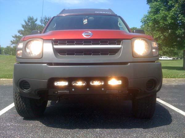
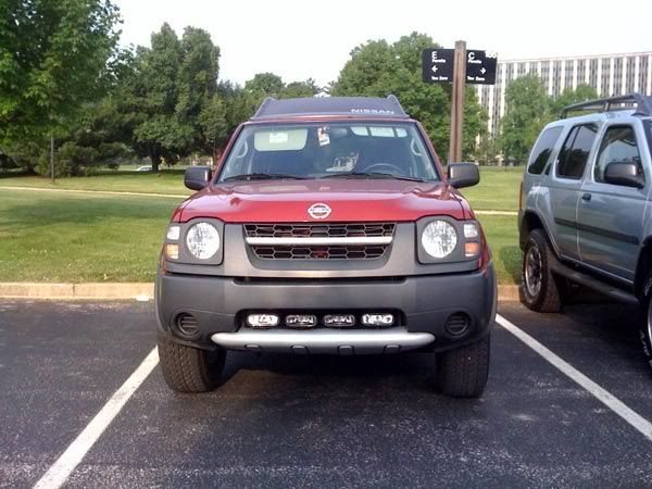
I was too impatient to wait for any aftermarket light bar for the bumper area of the Gen 1 so I decided to build one myself. This write-up is picture heavy to help everyone see what I did so that you can get ideas to build this even better. Here it is....
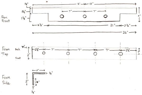
I started out with an idea of mounting some angled metal to the crossbar behind the gray plastic cover of the front bumper. Below you will see my mock-up drawings for the bar and the materials list attached. After that you will see how I wired it up and then a cross-section view of the mounting setup. These first five images are for reference to get you started. All of the following images illustrate my progress through the install.
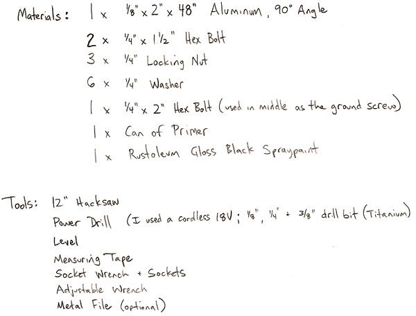
Light Bar Drawings and Material/Tools List
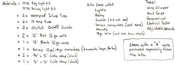
Wiring Diagram and Materials/Tools List

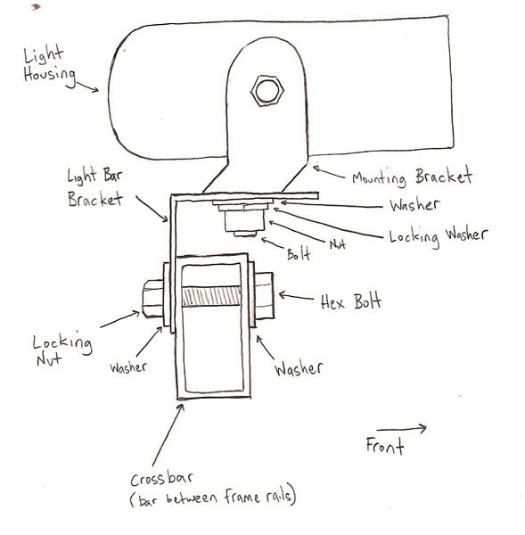
Crosscut View
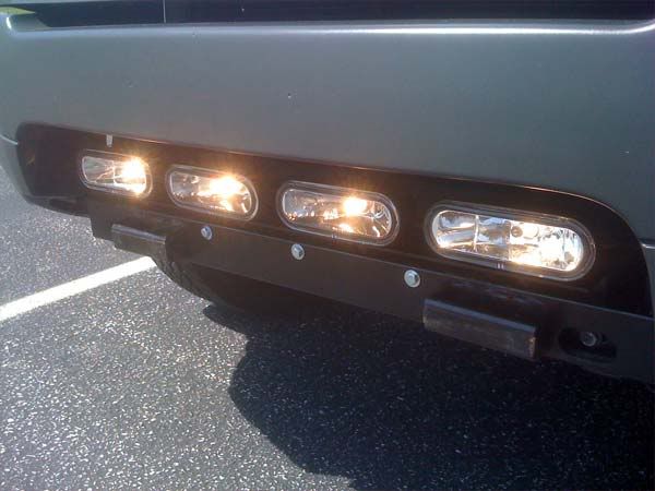
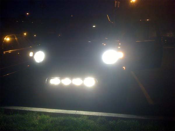
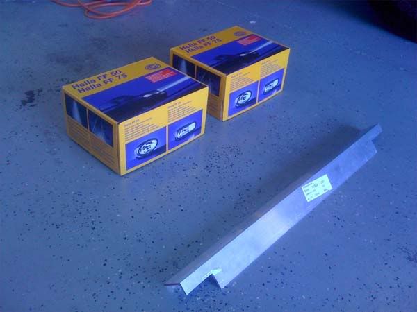
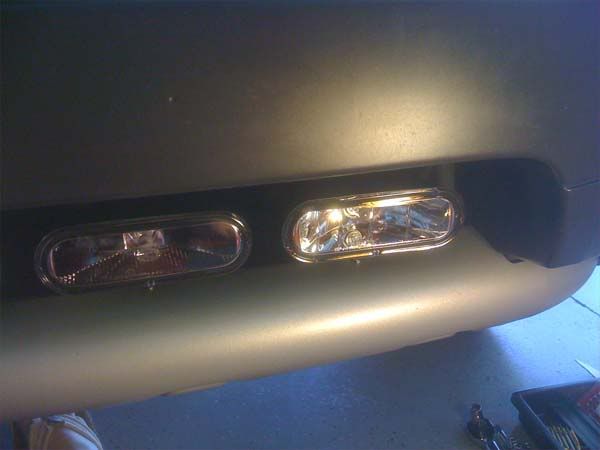
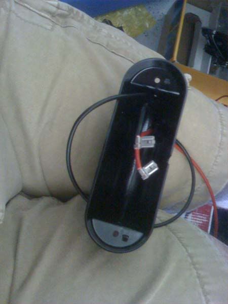
I chose a piece of angled aluminum to construct the bar from and decided to install a pair of Hella FF75 Driving Lights and a pair of Hello FF75 Fog Lights (I used the kits along with some additional materials). I cut the metal before taking a picture so I do not have a picture of it in raw form.
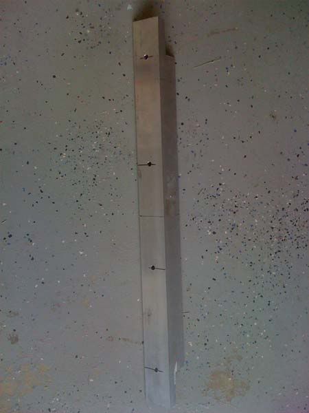
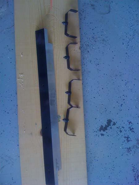
Used the drawings above to get the measurements I used on the aluminum to get the right shape. After measuring carefully, cut it and mark the holes to be used for mounting the lights.
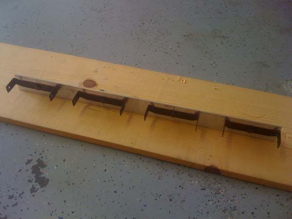
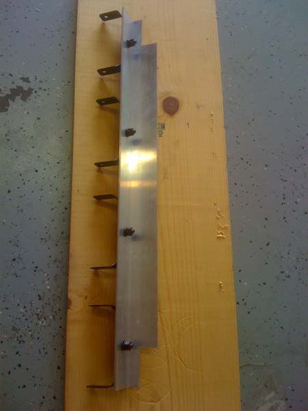
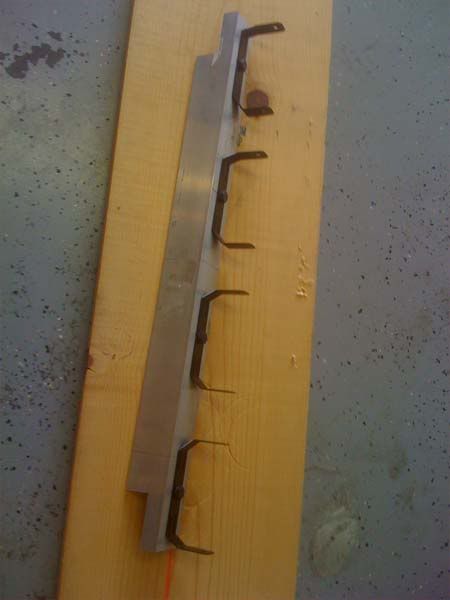
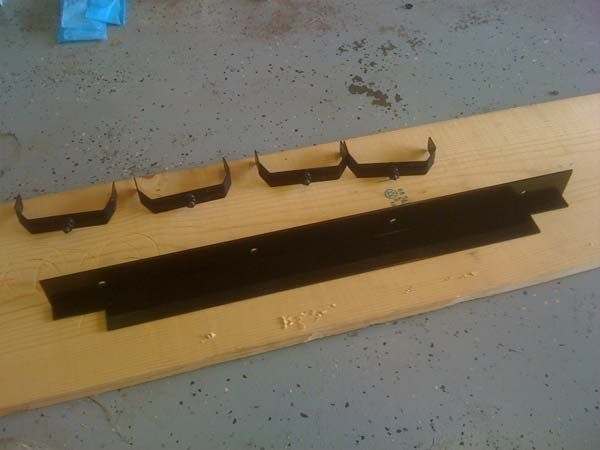
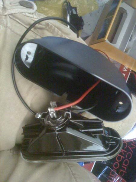
After drilling the holes I mocked-up the mounts to make sure they were good to go.
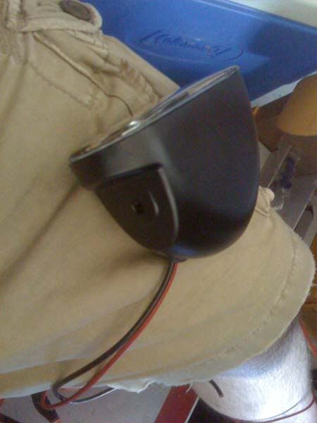
Then I painted the outward facing sides of the bar so that it would blend in with the truck. I used Rust-o-leum Glossy Black and primer.
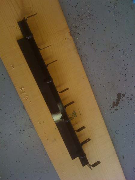
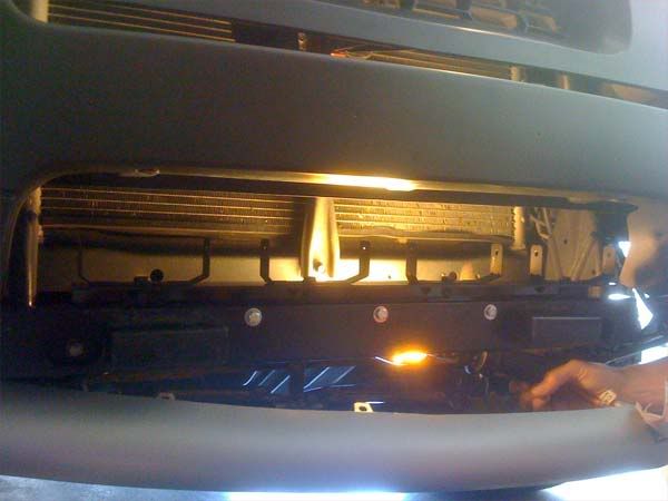
Once the light bar was cut, drilled and painted, it was time to get it mounted. Remove the gray plastic piece in the bumper to give yourself room to work.
I wanted to leave room to tuck the gray plastic piece underneath the light bar so I left space for it by using cardboard as a spacer as seen below.
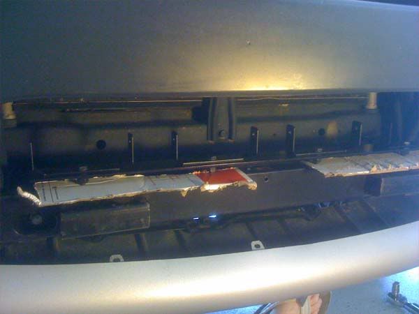
At this point I drilled the three holes that I used to mount the light bar to the crossbar. I drilled the first one on center and then measured 7 inches to the left and right and drilled the other holes there. Once they were done, I had a buddy hold the light bar where I wanted it and drilled through the crossbar holes again which made the marks I needed on the light bar. Once marked by the drill, I went and drilled the holes in the light bar. I then attached the light bar to the crossbar with the three bolts as seen below and also test fit the lights.
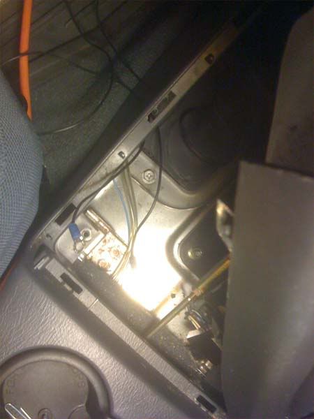
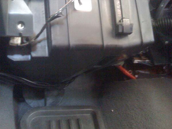
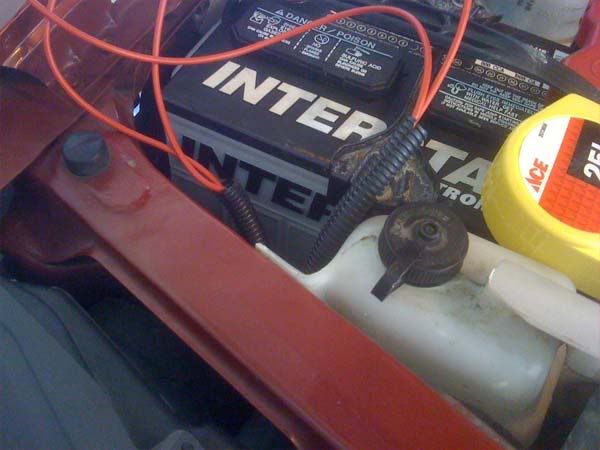
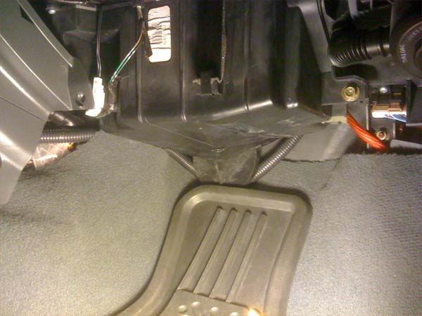
Now to the wiring. Please see my wiring diagram above for a more detailed view of what I did. My Xterra already had a hole in the firewall where the wiring for an amp was installed by the first owner. The hole was large enough to get six 18ga wires through it. Four of them were used for the switches and the other two will be used for future modifications. Another write-up maybe? You can see where the hole is below (this hole was later protected with a rubber grommit).
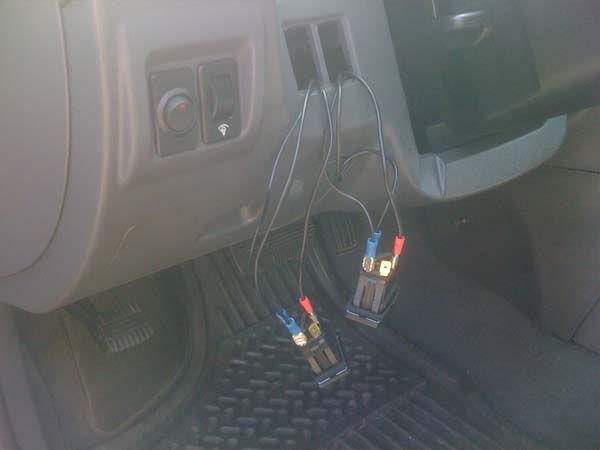
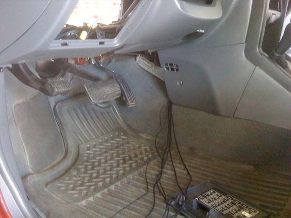
With the glove box removed, you can see where the wiring came into the front passenger floorboard.
And where I pull them over to the drivers floorboard...
These wires were connected to the battery, switches, and relays. Once I knew I could get wiring to the cabin, I started wiring the lights. I ran separate 12 gauge wires to each light and grounded the lights locally to the light bar. See below for more pics.
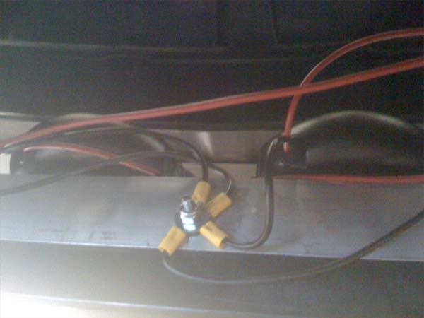
The middle mounting bolt was 1/2" longer than the other on purpose so I could use it as a common grounding point.
Once the lights were wired and mounted, I covered the wires with wire loom.
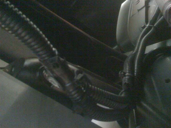
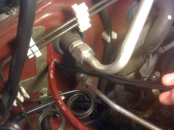
I brought the wiring up from the bumper, in through the passenger headlight area and into the engine compartment.
I followed my diagram and started working on the connections. Here is a picture of some of the wiring and the 15 amp fuses I used on each set.
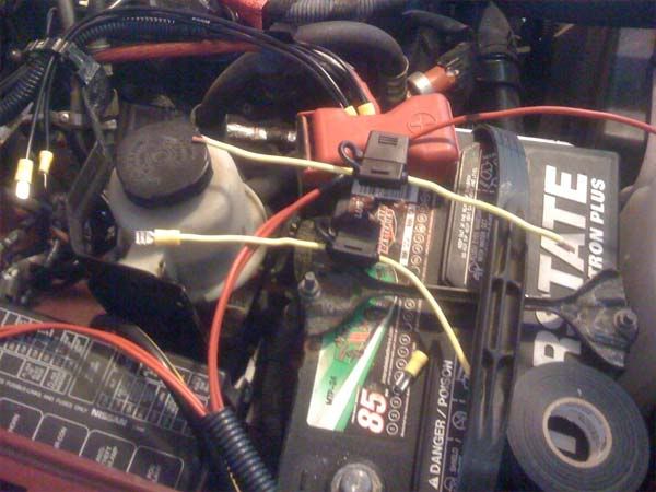
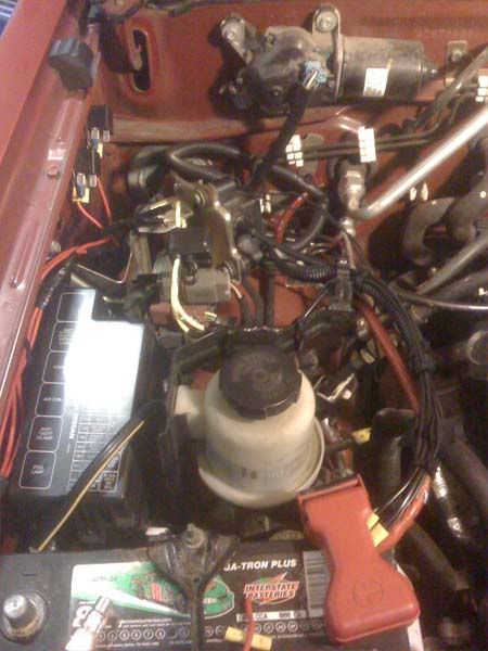
Here is a pic when it was almost done. I mounted the relays on the left back side of the engine compartment.
Once I was done in the engine compartment I cleaned up the wiring inside the cabin.
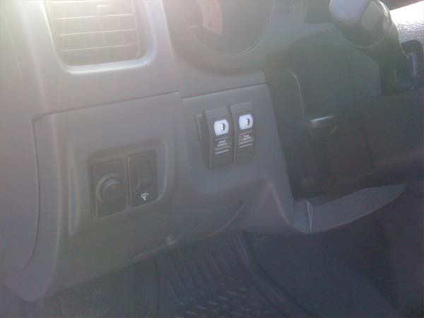
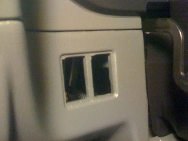
The switches from Oly4x4.com do not fit the dash holes unless you remove the notch in the upper-left corner of the holes. I used a small hacksaw blade to get them out as I don't have a Dremel (which I really want now).
[IMAGE LIMITATION: See next post]
I started out with an idea of mounting some angled metal to the crossbar behind the gray plastic cover of the front bumper. Below you will see my mock-up drawings for the bar and the materials list attached. After that you will see how I wired it up and then a cross-section view of the mounting setup. These first five images are for reference to get you started. All of the following images illustrate my progress through the install.
Light Bar Drawings and Material/Tools List
Wiring Diagram and Materials/Tools List
Crosscut View
I chose a piece of angled aluminum to construct the bar from and decided to install a pair of Hella FF75 Driving Lights and a pair of Hello FF75 Fog Lights (I used the kits along with some additional materials). I cut the metal before taking a picture so I do not have a picture of it in raw form.
Used the drawings above to get the measurements I used on the aluminum to get the right shape. After measuring carefully, cut it and mark the holes to be used for mounting the lights.
After drilling the holes I mocked-up the mounts to make sure they were good to go.
Then I painted the outward facing sides of the bar so that it would blend in with the truck. I used Rust-o-leum Glossy Black and primer.
Once the light bar was cut, drilled and painted, it was time to get it mounted. Remove the gray plastic piece in the bumper to give yourself room to work.
I wanted to leave room to tuck the gray plastic piece underneath the light bar so I left space for it by using cardboard as a spacer as seen below.
At this point I drilled the three holes that I used to mount the light bar to the crossbar. I drilled the first one on center and then measured 7 inches to the left and right and drilled the other holes there. Once they were done, I had a buddy hold the light bar where I wanted it and drilled through the crossbar holes again which made the marks I needed on the light bar. Once marked by the drill, I went and drilled the holes in the light bar. I then attached the light bar to the crossbar with the three bolts as seen below and also test fit the lights.
Now to the wiring. Please see my wiring diagram above for a more detailed view of what I did. My Xterra already had a hole in the firewall where the wiring for an amp was installed by the first owner. The hole was large enough to get six 18ga wires through it. Four of them were used for the switches and the other two will be used for future modifications. Another write-up maybe? You can see where the hole is below (this hole was later protected with a rubber grommit).
With the glove box removed, you can see where the wiring came into the front passenger floorboard.
And where I pull them over to the drivers floorboard...
These wires were connected to the battery, switches, and relays. Once I knew I could get wiring to the cabin, I started wiring the lights. I ran separate 12 gauge wires to each light and grounded the lights locally to the light bar. See below for more pics.
The middle mounting bolt was 1/2" longer than the other on purpose so I could use it as a common grounding point.
Once the lights were wired and mounted, I covered the wires with wire loom.
I brought the wiring up from the bumper, in through the passenger headlight area and into the engine compartment.
I followed my diagram and started working on the connections. Here is a picture of some of the wiring and the 15 amp fuses I used on each set.
Here is a pic when it was almost done. I mounted the relays on the left back side of the engine compartment.
Once I was done in the engine compartment I cleaned up the wiring inside the cabin.
The switches from Oly4x4.com do not fit the dash holes unless you remove the notch in the upper-left corner of the holes. I used a small hacksaw blade to get them out as I don't have a Dremel (which I really want now).
[IMAGE LIMITATION: See next post]