
- Location
- Bloomington, IN
How to replace the PIAA 525 OEM switch with a Carling Tech type switch.
Obviously, there are many variations of this type of install; this is only how I chose to do it.
You will need the following for this writeup:
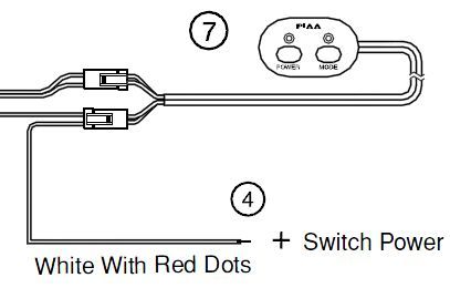
- PIAA 525 lamp set with all OEM wiring and relays: Link to PIAA website
- Carling Tech SPDT switch: Link to OTRATTW website
I got the following part numbers; Product ID: VVPZCG2-50R, Switch Selection : V6D2UHCB - SPDT ON/OFF/ON, GREEN/RED
- An available switch slot in your dash
Information:
Look at the install instructions and make sure you have all of the necessary wiring for the PIAA 525 set.
Link to Instructions (PDF)
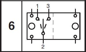
Familiarize yourself with the switch wiring diagram (V6D2UHCB):
Link to all Carling Tech circuit diagrams (PDF)
Install Steps:
1. Install the PIAA 525 per the instructions given. Any guidance for that is outside the scope of this writeup [PM me if you need help]. Instead of putting the OEM switch in the cab, just install everything and leave the OEM switch sitting in the engine bay.
2. Test the lamps in this configuration (before cutting off OEM switch).
3. If the lamps work, proceed to 4. [Remember to disconnect power!]
4. Cutoff the OEM switch leaving about 3 inches of wiring on the switch (in case you want to reverse this modification).
5. Feed the wire through the firewall and into an open switch tab in the dash.
6. Wire up the switch like the diagram below.
7. Test and drink a beer!
Install Step Details:
1. Self explanatory; Pic for reference:
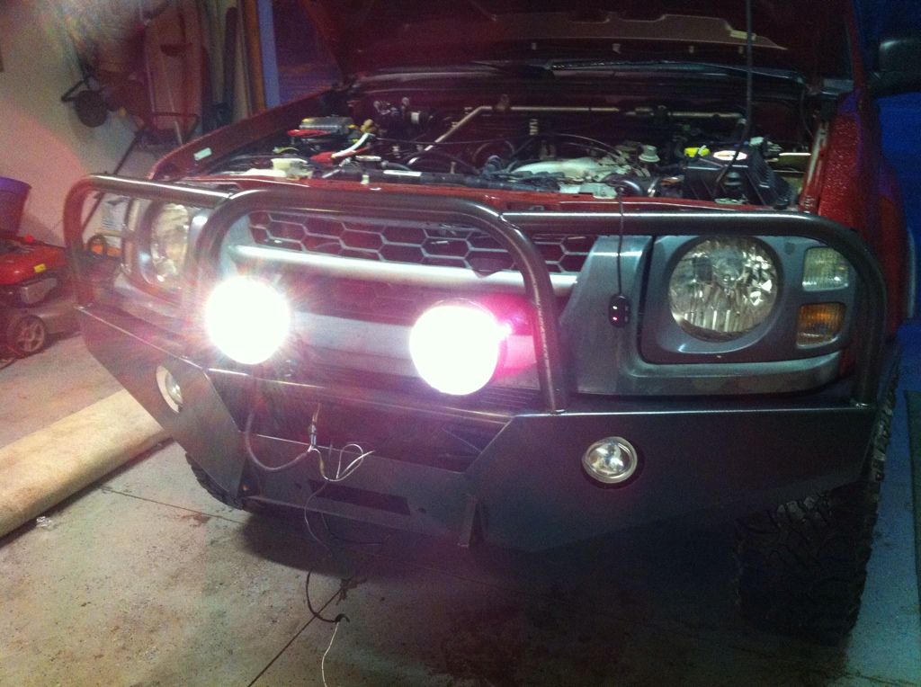
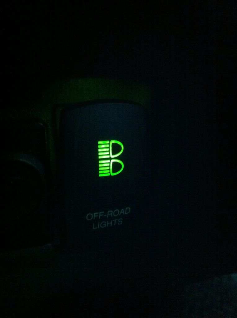
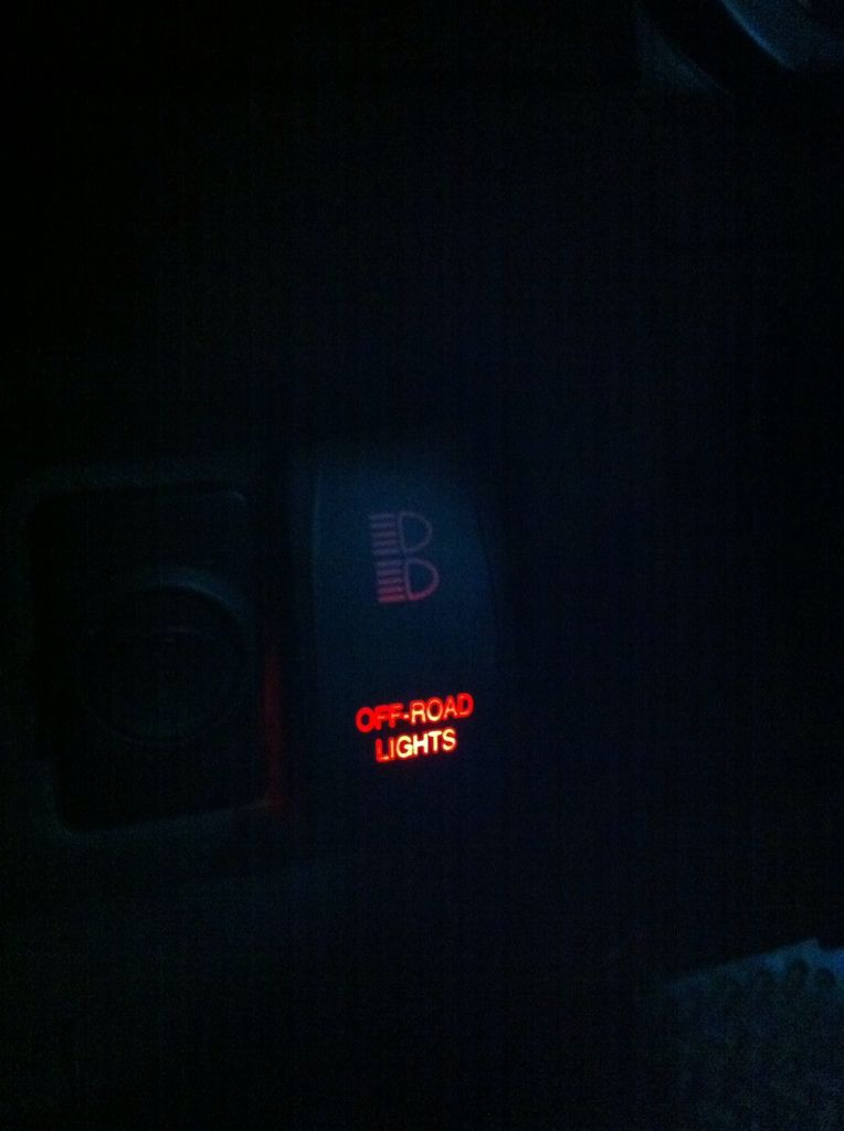
2. Refer to pic above. Lamps should work (High beam, low beam, LED) and switch should light up.
3. No need to repeat myself.
4. Just do it! [You can always revert this by splicing the OEM switch back to the OEM cabling.
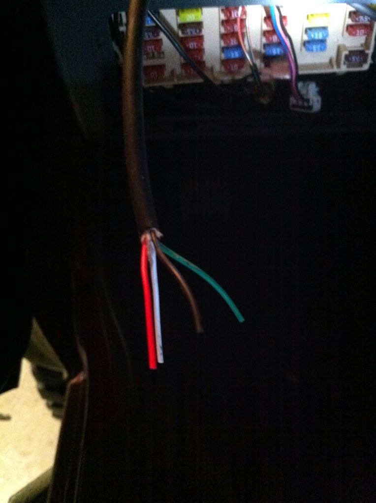
5. Wire Descriptions:
Red = Input power (+) to the switch (to trigger relays)
Black = Ground (-) to the switch (used for switch LED grounds)
Green = Low Beams (I think)
White = High Beams (I think)
6. Switch wiring diagram:
Original wiring:
New wiring:
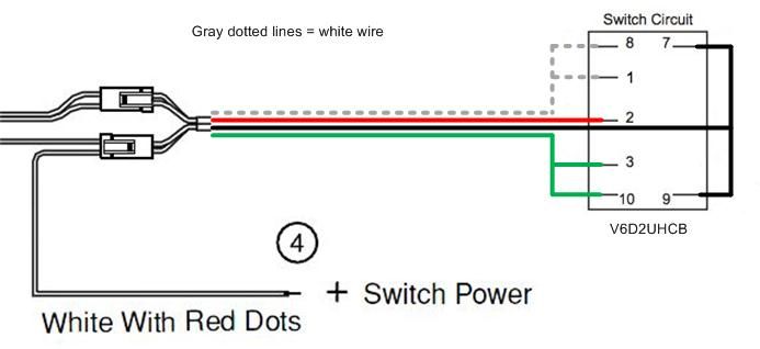
Incoming RED > Connect to only #2 (brings power to the switch)
Incoming BLACK > Connect the same wire to #7 and #9 (creates a ground for the switches 2 LED's)
Incoming GREEN > Connect the same wire to #3 and #10 (when the switch is flipped, power leaves #3 to power the relay and the pigtail going to #10 gives the LED power to turn on when the lights are on)
Incoming WHITE > Connect the same wire to #1 and #8 (when the switch is flipped, power leaves #1 to power the other relay and the pigtail going to #8 gives the other LED power to turn on when the lights are on)
7. Cheers!
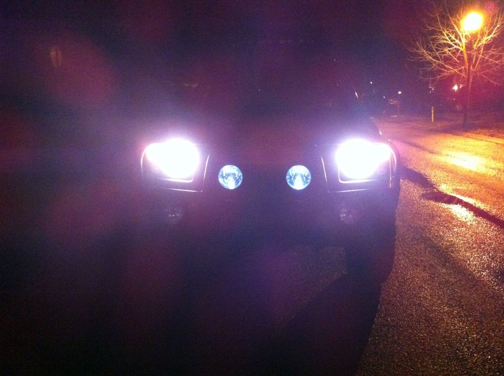
Final Pics:

PM me if you need additional information.
Obviously, there are many variations of this type of install; this is only how I chose to do it.
You will need the following for this writeup:
- PIAA 525 lamp set with all OEM wiring and relays: Link to PIAA website
- Carling Tech SPDT switch: Link to OTRATTW website
I got the following part numbers; Product ID: VVPZCG2-50R, Switch Selection : V6D2UHCB - SPDT ON/OFF/ON, GREEN/RED
- An available switch slot in your dash
Information:
Look at the install instructions and make sure you have all of the necessary wiring for the PIAA 525 set.
Link to Instructions (PDF)
Familiarize yourself with the switch wiring diagram (V6D2UHCB):
Link to all Carling Tech circuit diagrams (PDF)
Install Steps:
1. Install the PIAA 525 per the instructions given. Any guidance for that is outside the scope of this writeup [PM me if you need help]. Instead of putting the OEM switch in the cab, just install everything and leave the OEM switch sitting in the engine bay.
2. Test the lamps in this configuration (before cutting off OEM switch).
3. If the lamps work, proceed to 4. [Remember to disconnect power!]
4. Cutoff the OEM switch leaving about 3 inches of wiring on the switch (in case you want to reverse this modification).
5. Feed the wire through the firewall and into an open switch tab in the dash.
6. Wire up the switch like the diagram below.
7. Test and drink a beer!
Install Step Details:
1. Self explanatory; Pic for reference:
2. Refer to pic above. Lamps should work (High beam, low beam, LED) and switch should light up.
3. No need to repeat myself.
4. Just do it! [You can always revert this by splicing the OEM switch back to the OEM cabling.
5. Wire Descriptions:
Red = Input power (+) to the switch (to trigger relays)
Black = Ground (-) to the switch (used for switch LED grounds)
Green = Low Beams (I think)
White = High Beams (I think)
6. Switch wiring diagram:
Original wiring:
New wiring:
Incoming RED > Connect to only #2 (brings power to the switch)
Incoming BLACK > Connect the same wire to #7 and #9 (creates a ground for the switches 2 LED's)
Incoming GREEN > Connect the same wire to #3 and #10 (when the switch is flipped, power leaves #3 to power the relay and the pigtail going to #10 gives the LED power to turn on when the lights are on)
Incoming WHITE > Connect the same wire to #1 and #8 (when the switch is flipped, power leaves #1 to power the other relay and the pigtail going to #8 gives the other LED power to turn on when the lights are on)
7. Cheers!
Final Pics:
PM me if you need additional information.
Last edited: